Power output point

This is a very simple project, but maybe other people can use the idea.
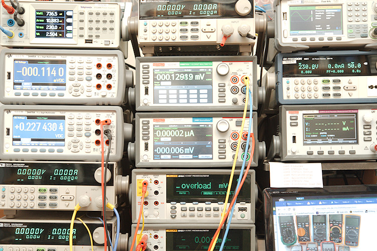
On my main workbench I have lot of bench meters, electronic loads and other stuff, this gives me a bit of an issue with my power supplies, because I want very short wires from them (or remote sense).
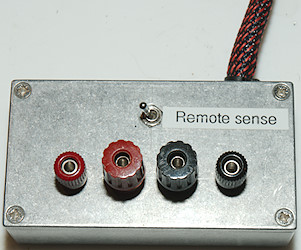
With the Keithley precision power supply I made the above box when I got the supply, mostly because it only had remote sense on the back.
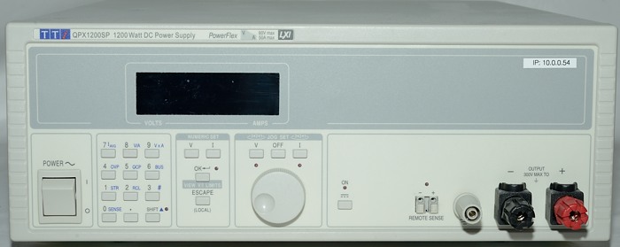
But for my big supply, that is way to big to be close to my working space, it is about one meter from my work area. I had some binding binding posts at the end of a thick cable, but without remote sense. That is two problems: one is the lacking remote sense, the other is that binding posts cannot handle the full current of the supply.

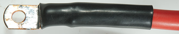
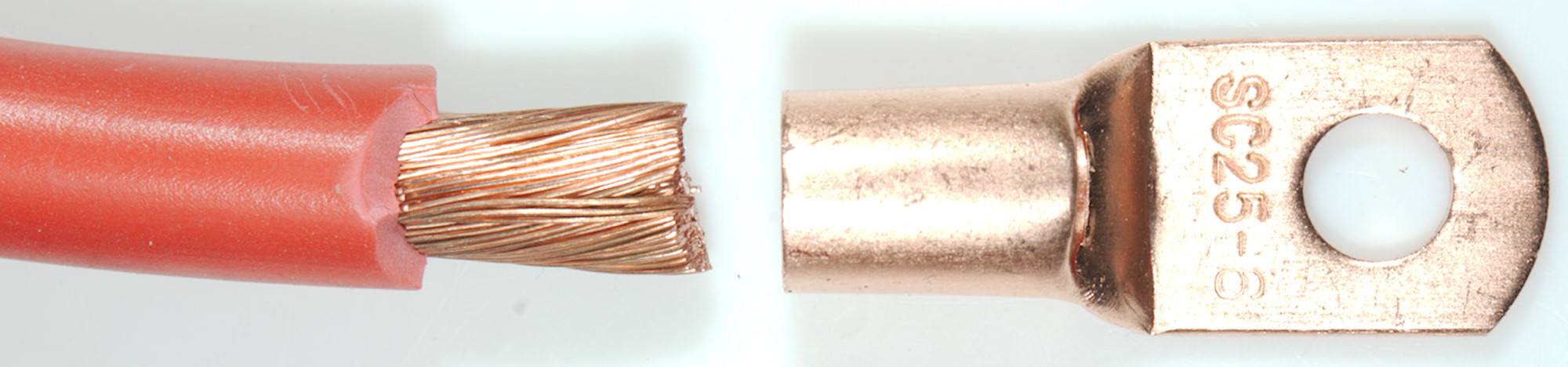
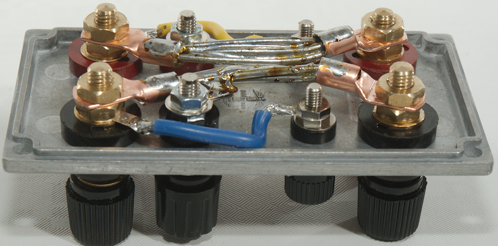
First I made some cable with connection that could handle full current, the cable is 25mm2. I do not have any tool to crimp that with and instead I soldered it (That is not the ideal way).
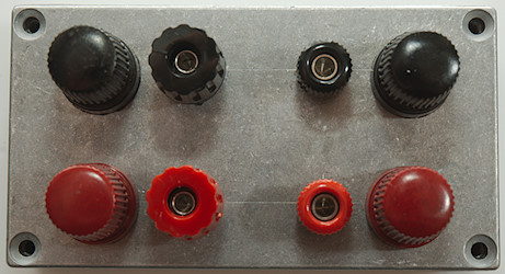
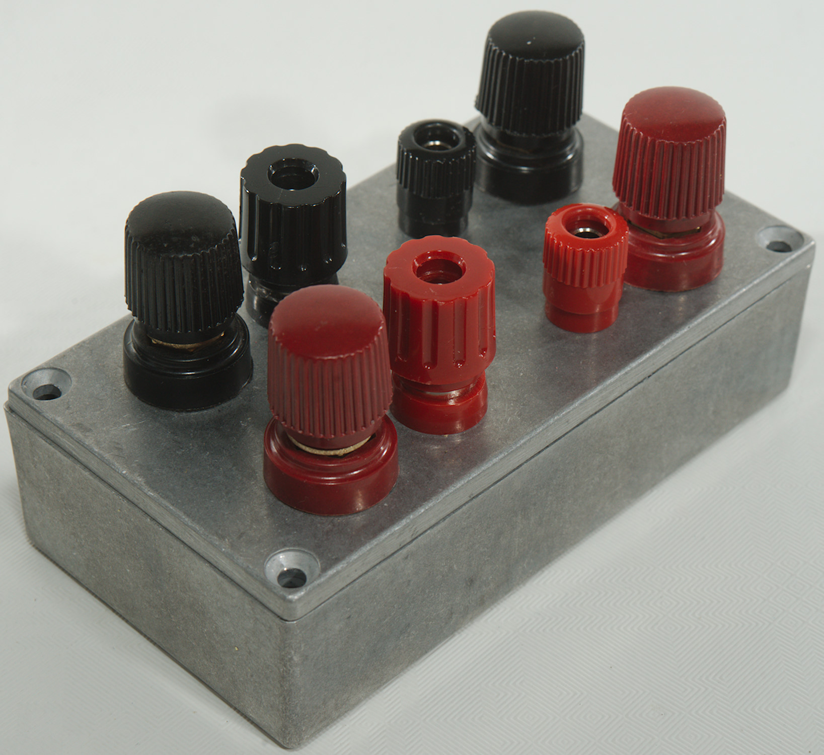
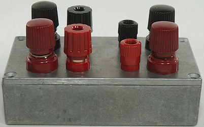
I wanted input and remote sense for connection to the power supply and for the output both regular binding post and some high current types.
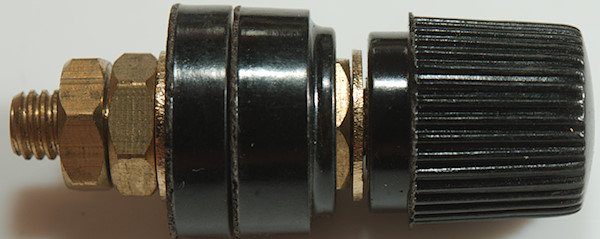
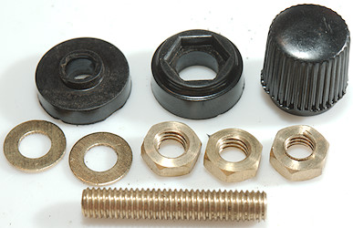
For the high current binding post I found some on ebay, they are rated for 100A or 200A (The low value in specifications, the high in headings).
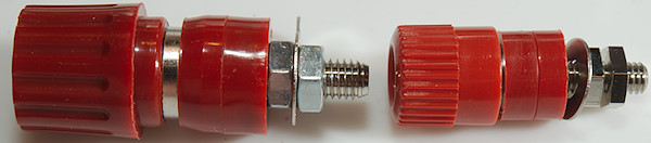

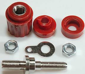
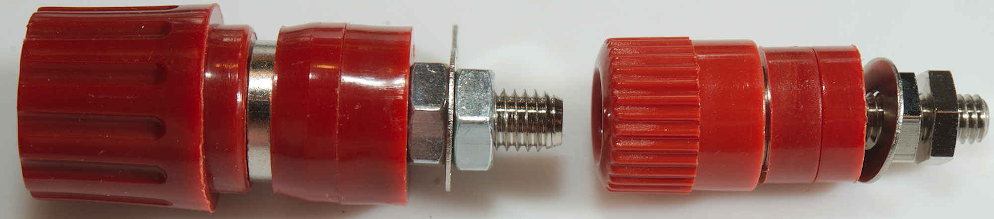
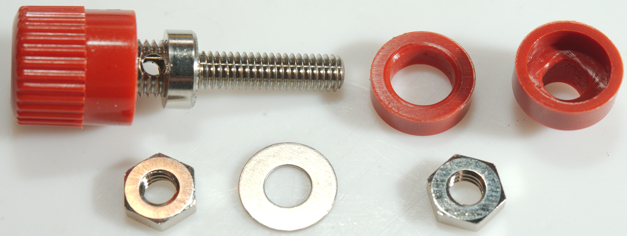
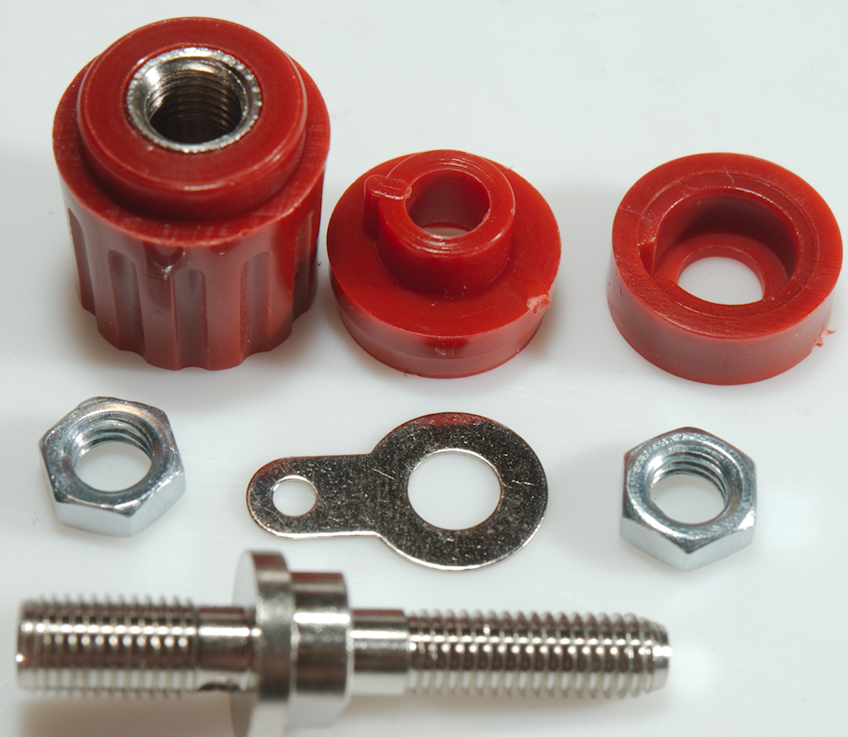
For the regular binding posts I uses the models I always uses, the large model is rated 30A the small model 20A and the treads are in metal.
The small is for sense, the large is for output.
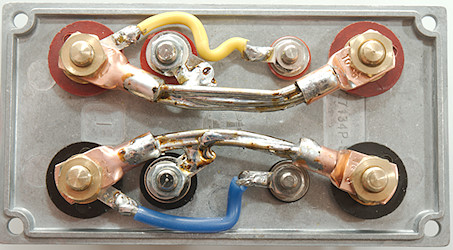

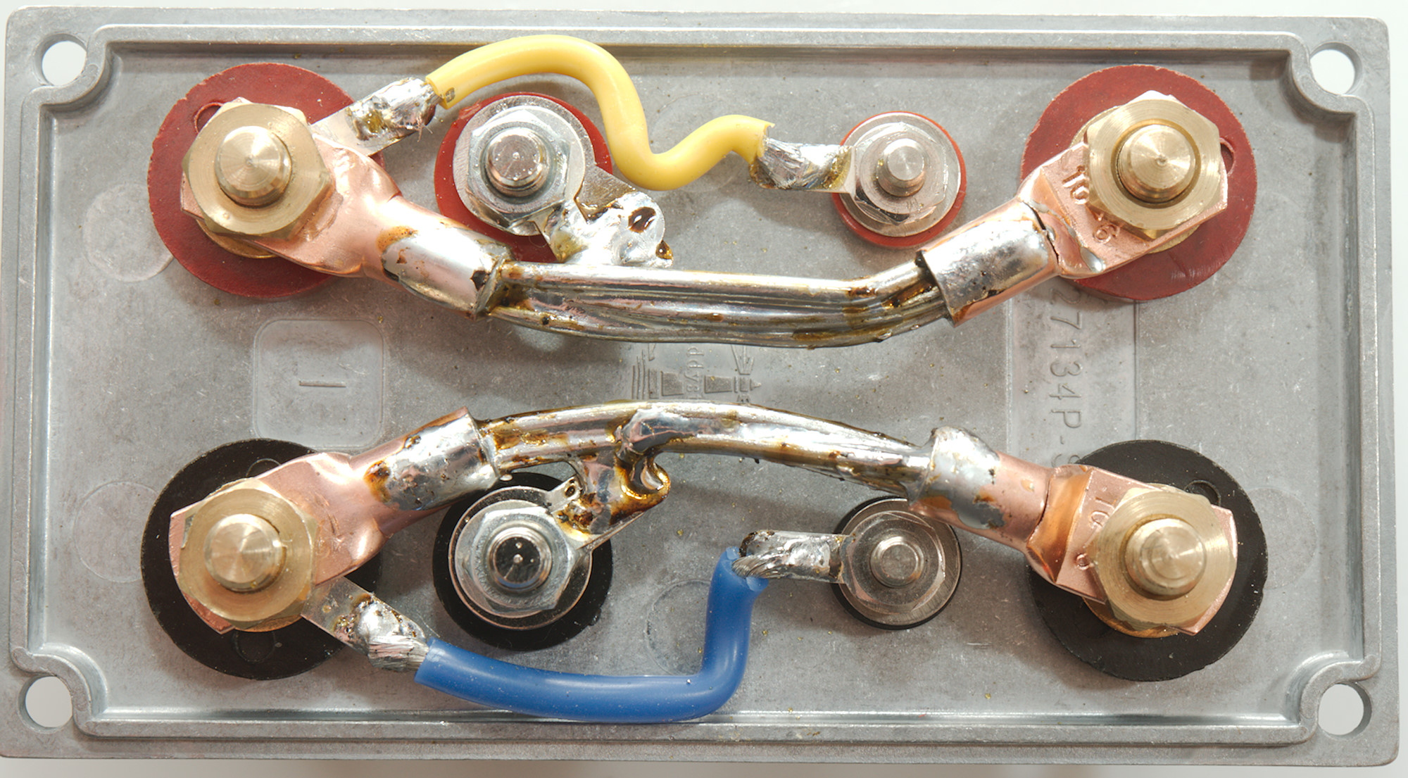
I wanted some very solid connections between the different connectors and the sense got a separate connection from the output binding posts.
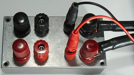
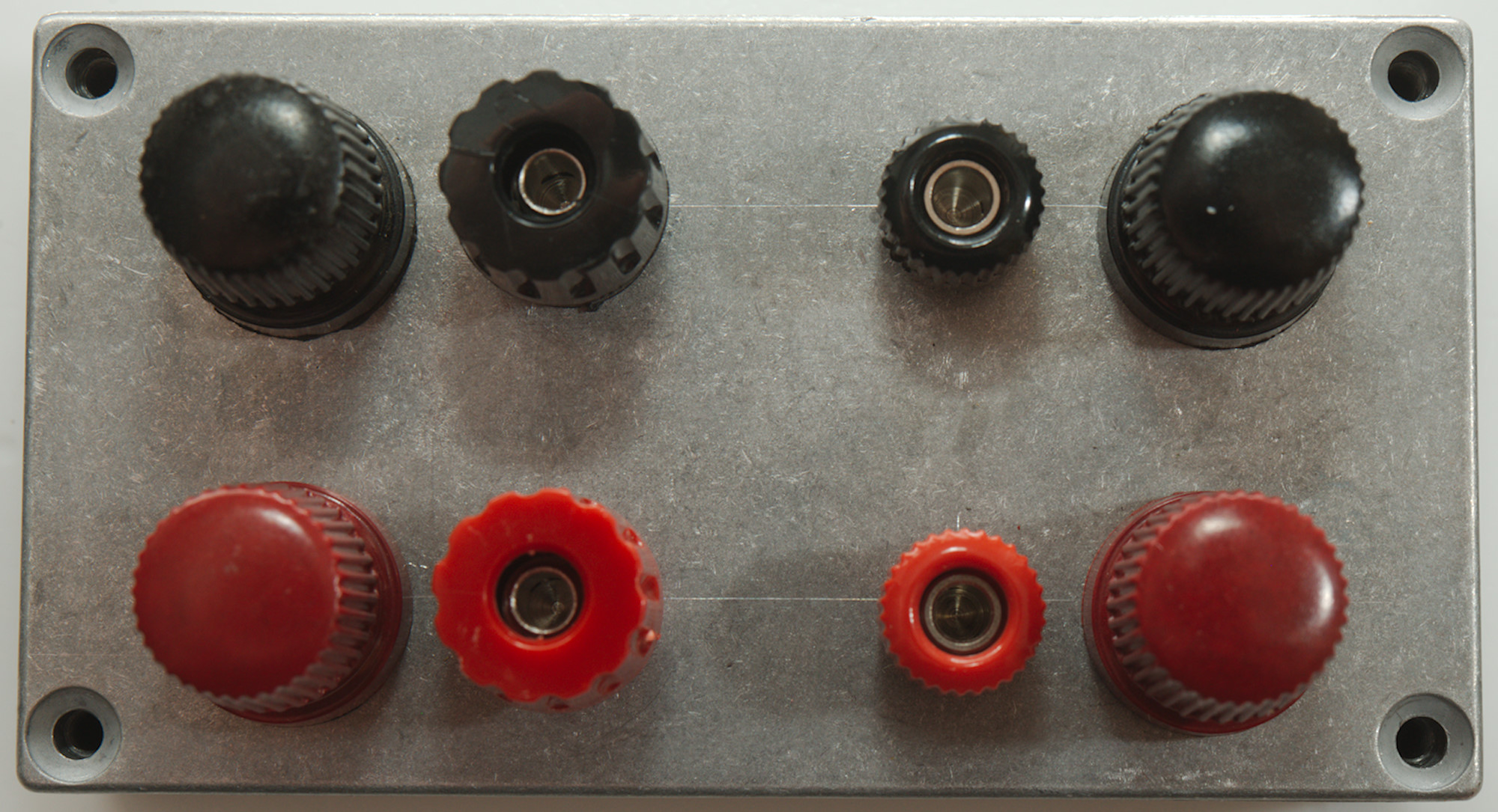
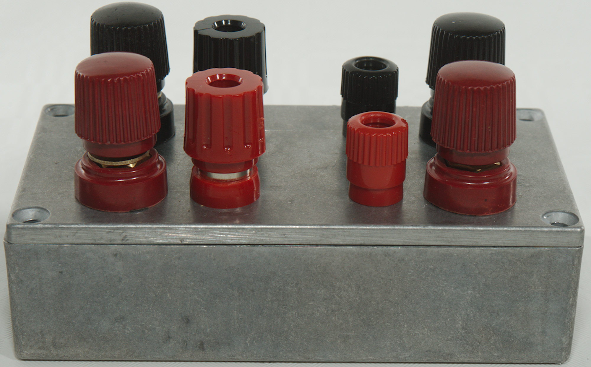
Ready to use with high current input and sense feedback.
Measurements
There is not much to measure, but I adjusted the current on my supply to maximum and low output voltage, then I shorted the output binding post with a short thick copper wire:
- Output current: 50A
- PS voltmeter without remote sense: 0.45V
- PS voltmeter with remote sense: 0.038V (This matched the remote sense output).
- Output from PS: 0.25V
- Measured at box input: 0.071V
- Measured at box output: 0.021V (This is the voltage across the short).
Even though the remove sense is connected to the bottom of the binding post I still looses 10mV across it and the connection to the shorting copper wire (that is 0.2mOhm).
The 0.071V at the input means I looses about 2.5 Watt in the box.
A voltage test:
- Unloaded output voltage at screw only binding posts: 6.007V
- Loaded 30A on banana plug binding post, voltage on screw only binding posts: 6.007V
Remote sense works very nicely, the voltage at this output box is stable.
Conclusion
With this box I do not need a voltmeter to check input voltage or do any load depend voltage compensation on the power supply, the voltage I set on the power supply is the voltage I have at my working point. If I need to compensate a few extra connections I can easily move my remote sense point now.
The other advantage is that I can use all 50A for testing.
Notes
The two power supplies are:
The small one: Keithley 2280S-32-6: 32V 6A with precision voltage and current meters
The large one: TTi QPX1200SP: 1200W 60V 50A (U*I is limited to 1200W).